


Using the Identification Tab
The details of the screen element captured using Real-Time Designer are displayed in the center of a window in the Identification tab.
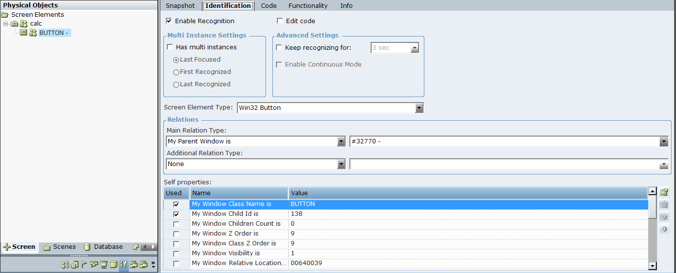
Each field in the Identification tab is automatically identified by Real-Time Designer to represent the selected screen element. You can modify them, if needed, but this is typically not required. The fields displayed may differ according to the type of application and type of screen element selected. You can assign a business entity to a property value (the business entity must have an initial value assigned to it). This enables dynamic identification of a screen element during runtime.
The following basics fields appear in the Identification tab:
Enable Recognition
When you have a lot of captures and want to exclude a capture for performance reasons.
When you have more than one solution loaded by the same client, but only one solution should be active at any given time and you want to control for which of these solutions the screen elements are enabled. This is typically relevant for Robotic solutions when a Robot has more than one solution assigned, but runs only one solution at a time based on the task it gets.
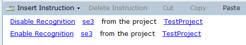
In runtime, you can use the Enable Recognition and Disable Recognition functions to enable or disable recognition of specific screen elements.
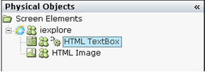
If you have two screen elements with same description, for example, two captures of iexplore process, then the behavior is as follows:
If recognition of both are disabled and you enable one of them, only that one is recognized.
If both are currently recognized and you disable recognition for one of them, then BOTH are disabled. If the target application is closed and reopened, then only the screen element for which recognition wasn’t disabled is recognized.
Recommendation for Robotic Projects: If you have more than one solution assigned and want to use Enable/Disable Recognition to control which one is used, the best practice is as follows:
By default, disable recognition for all screen element roots (process level).
When a solution becomes active (task arrives), enable recognition of all screen element roots (process level) of the solution.
When a solution is done (completed task handling), disable recognition of all screen element roots (process level) of the solution.
The Enable Recognition and Disable Recognition functions are located under Library Objects > Connectivity, see Library Objects Reference.
During runtime, you can see which screen elements are in a deactivated state: use the Log Screen Elements function of the Process screen element. For example:
<se2 Deactivated="True" MI="" ActivePO="" POs="" />
<se3 Deactivated="False" MI="" ActivePO="Win32_3603D8:6" POs="Win32_3603D8:6" />
Edit Code
Edit code: Enables you to make changes to the code in the Code tab. This option is not selected by default.
The Edit code option is designed for advanced users only.
When Edit code is selected, the Screen Element Type definition as well as the Relations and Self properties areas are grayed-out and not enabled for editing on the Identification tab. This is because the screen element identification uses code in the Code tab and this code becomes editable. For details, see Using the Code Tab.
In addition, when Edit code is enabled for a screen element, the  icon is displayed in the Screen Elements tree for that screen element. This icon enables you to quickly identify those screen elements whose code has been edited in the Screen Elements tree.
Multi Instance Settings
Has Multi Instances: Indicates whether the screen element has multiple instances in real-time. For more details on how to use multi-instance functionality, see Multiple Instances.
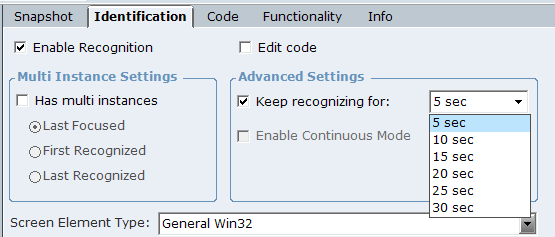
Advanced Settings
Keep recognizing for: Select this option to continue recognizing a screen element for a set time interval after the parent screen element is initially launched (triggered). For example, an application's internal windows are slow to open due to slow connections with the server or the window is designed to open with a delay. Available time intervals are 5, 10, 15, 20, 25, and 30 seconds. If the screen element appears when the specified time for keep recognizing is over, it is not recognized.
In most cases using this option is not required and enabling it can impact performance as recognition attempts are done in a loop for the specified interval. Before enabling this option, consult with your Connectivity Expert.
In the RTClient log, the messages are repeated each second during the time frame specified for the keep recognition option:
[Connectivity Thread] DEBUG ScreenConnectors - CONN: DoRecognizeDescriptorAndPoSubtree - Begin, Only this Desc: 'TestProject.se3'
[Connectivity Thread] DEBUG ScreenConnectors - CONN: Enumeration query returned: '0'
[Connectivity Thread] DEBUG ScreenConnectors - CONN: DoRecognizeDescriptorAndPoSubtree - End, desc: 'TestProject.se3'
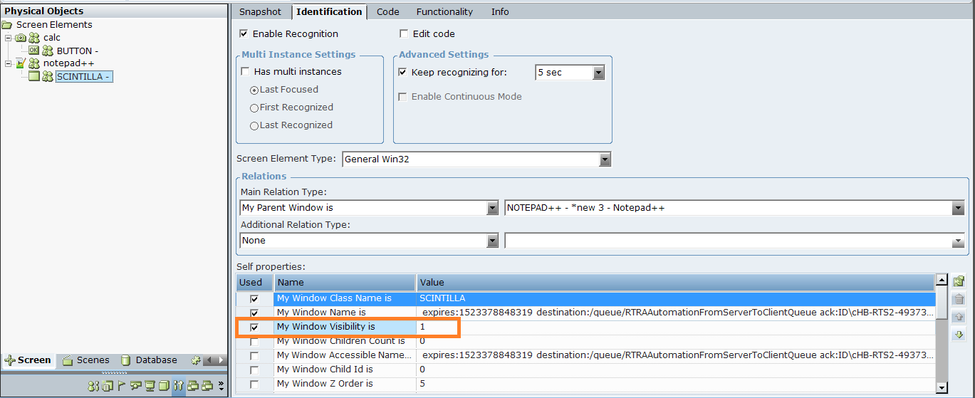
To enable continuous recognition of a screen element based on its visibility, you must clear the Keep recognizing for option in the Advanced Settings area and set the My Window Visibility is self property to 1. The behavior is then as follows during runtime: when control is hidden in the target application, the screen element is not recognized; when the control becomes visible, the screen element is recognized.
Enable Continuous Mode: Select this option in the Advanced Settings area when your HTML element is dynamic and the properties can change without events being raised. This option enables polling (values are refreshed every second) for the following properties of the Generic HTML screen element: Inner HTML, Inner Text (in some cases this is a Value), Enabled, and Visible. This option is cleared and disabled for specific screen element types, for example, for the Generic HTML Document screen element.
Screen Element Type
Screen Element Type: Real-Time Designer automatically identifies the type of a screen element and shows the element's classification (for example, HTML TextBox, Win32 Edit) in the Screen Element Type drop-down list. For a complete list of the screen element types that can be identified.
Relations
Main Relation Type: This definition indicates the relationship between the selected screen element in the Screen Elements tree and other screen elements in the hierarchy. For details, see Main Relation Type.
Additional Relation Type: This option enables you to identify a screen element by its location relative to the other screen elements on the third-party application screen. This option is not enabled for all connector types and extensions. For details, see Additional Relation Type
Self Properties
Self properties: This area lists the properties that can be used to uniquely identify this screen element. Real-Time Designer automatically selects the property that it determines is the best for identifying the screen element. You can assign a business entity to a property value (the business entity must have an initial value assigned to it). This enables dynamic identification of a screen element during runtime. For example, this enables you to capture a single screen element and then use a business entity to reference a similar screen element with a different name. For details, see Self Properties
Main Relation Type
The drop-down list contains the listed relation types. This list corresponds to a selected screen element’s type and differs for each connector type. The drop-down list displays a hierarchy of all captured screen elements, which also includes all hidden screen captures:
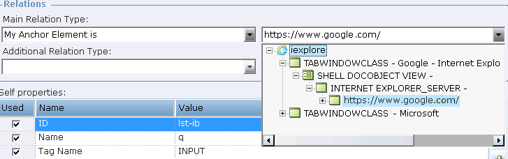
This hierarchy in the drop-down list reflects the hierarchy in the Screen Elements tree.
The hidden screen captures in the screen element drop-down list are displayed according to their hierarchy, regardless of whether the Show Hidden Captures option is selected for a root process in the Screen Elements tree.
Typically, you only need to change a related screen element in the screen element drop-down list when there is no stable ID or name and the location is dynamic. In this case, you should select another element on the page whose relationship is stable.
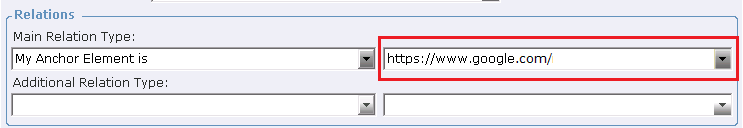
For example, for web application screen elements only, you can change the Main Relation Type value to use a different XPath than the one that is automatically calculated. See Using the Web Connector for IE
Additional Relation Type
Other screen elements should be captured in order to use them in Additional Relation Type.
For some connectors, the Additional Relation Type drop-down lists are disabled, for example, Internet Explorer, Firefox, and Chrome connectors.
By default, when you capture screen element, the value of the Additional Relation Type is None. You can change this if you specify an additional relationship.
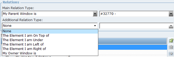
The following additional relation types are available for selection and are common to all screen elements types that support this option:
The Element I am On Top of: The screen element is on top of the screen element selected from the adjacent drop-down list.
The Element I am Under: The screen element is under the screen element selected from the adjacent drop-down list.
The Element I am Left of: The screen element is to the left of the screen element selected from the adjacent drop-down list.
The Element I am Right of: The screen element is to the right of the screen element selected from the adjacent drop-down list.
The Owner Window is: Enables you to identify a window based on its owner window. To specify this property, select the My Owner Window Is relation type from the drop-down list, and then specify the owner window in the adjacent field. The owner may be the desktop itself or another window.
For example, the following procedure describes how to define an additional relation type for a button captured in the Windows standard calculator window.
To define an additional relation type:
| 1. | Open the Calculator application. |
| 2. | Open the Screen Element definition window (see Screen Element Definition Window). |
| 3. | Click Capture and capture Button 5. |
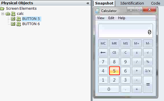
| 4. | Click Capture and capture Button 6. |
| 5. | Select the screen element captured on the Screen Elements tree and click the Identification tab. |
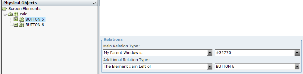
| 6. | From the Additional Relation Type drop-down list, select The Element I am Left of item. |
| 7. | From the drop-down list to the right of the Additional Relation Type drop-down list, select Button 6: |
| 8. | Click Locate. Real-Time Designer is minimized and Button 5 is marked by a blinking rectangle in the Calculator window. |
The Self properties grid lists the properties that can be used to uniquely identify a screen element. Real-Time Designer automatically selects the property that it determines is best to use to identify the screen element by checking the relevant self property in the Used column. You can select additional properties if you determine that these properties are needed (typically they are not).
You can assign a business entity to a property value (the business entity must have an initial value assigned to it). This enables dynamic identification of a screen element during runtime. For example, this enables you to capture a single screen element and then use a business entity to reference a similar screen element with a different name.
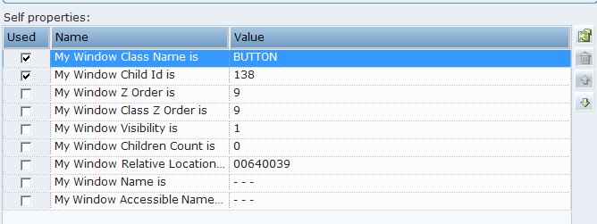
It is recommended to avoid selecting too many options so as not to slow down the process of the target application. An example of Self properties for a Win32 connector type are displayed below:
By default, Real-Time Designer has a default order for listing the self-properties in the Self properties pane. When Real-Time Designer checks the list of properties to identify a screen capture, it works from the top of the list downwards, and only checks the self-properties in use (selected). The self-properties that are selected are placed at the top of the list, and have an AND relationship between them.
The default order of Self properties can be changed for each connector type in the Real-Time Designer’s System Settings window. See Defining Real-Time Designer Screen Connectivityin the detailed in the System Administration Guide for details.
You can perform the following operations using the toolbar in the Self properties pane:
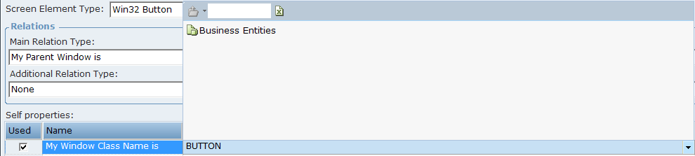
Assign Business Entity to a Value
To assign a business entity to a property value, select the required business entity from the drop-down list at the top of the pane. The business entity must have an initial value assigned to it.
Add Value
The Add Value enables you to add another value to a self property. To do so, select the self property row where you want to add another value, and click to add a row to the Self properties pane. Then, enter a new value for the property. You do not need to enter the property name, only the new value.
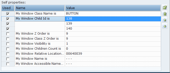
Multiple values for a self-property have an OR relationship between them. Consider an example where you want to add two other values to the My Window Child Id is property in addition to its current value, which is 138. The example below shows that a second value (139) and a third value (140) were added to the My Window Child Id property.
Move Up and Move Down
You can reorder the self properties or values of self property listed in the Self properties grid, as required, using the Move Up  and Move Down
  arrows on the toolbar.
Remove Value
The Remove value function  deletes the selected property’s value from the Self properties pane. You can remove only the values of those self properties where you have added new values.
When a self property has only one value, you cannot remove this value. Additionally, you cannot remove the entire self property in the Self properties grid.